Diesel Place banner

Dual Electric Cooling Fans Installed

24K views 60 replies 20 participants last post by  Rafedial1  
#1 ·
Hello All,

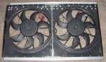
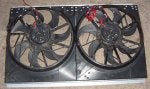
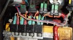
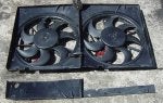
I finally completed my dual electric cooling fan installation. I used two (2) Bosch (manufactured for Volvo p/n 8649522) fans obtained from fleaBay. Each fan has an all-enclosed plastic shroud (see note later on this important feature), silent S-blades, a powerful motor that draws 18 amps and a 3,000+ CFM rating.

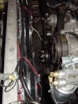
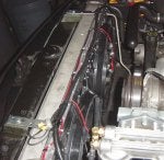
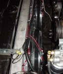
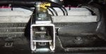
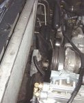
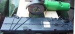
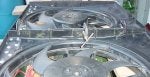
Pics #1 and #2 show the stock fan shrouds (upper and lower) removed from engine compartment. The first shows the clearance of the fan clutch from the radiator. The second shows a rear perspective of the radiator – if you zoom in to the bottom of the radiator, you can just about see the 1/4" gap, about 3/4" deep, between the radiator and the lip of the radiator support. This will be used to anchor the base of the dual electric fan assembly
 

Attachments

#2 ·
Pics #3, #4 and #5 show the plastic shrouds cut to fit the height of the radiator, which measures 20” high. The cut pieces are further trimmed and will be reattached to the plastic shroud to maintain the all-enclosed feature. That’s a metal cutting disc on the angle grinder.
 

Attachments

#3 ·
The radiator measures 34” in width. Each fan is 17” and bit in width. In order for the two fans to fit, they have to be trimmed a bit and I chose to do this where they will be attached. Pic #6 shows the fans where they will be cut and trimmed at alternating sections (I first used the metal cutting disc but resorted to a hacksaw for cleaner cuts).

An “X” indicates a waste section to be cut/discarded. The corresponding section on the other fan will be retained. An unmarked section will be retained. Its corresponding section on the other fan will be indicated with an “X” and cut/discarded. This trimming will be just enough for the assembly to fit snugly in between the radiator side tanks (well, okay, I cheated at 3:00 a.m. and used a blow torch on one corner to soften the material enough…).
 

Attachments

#4 ·
Wow Franko, that looks serious. How are you going to control the fans turning on and off?

Rob :)
 
#13 ·
Wow Franko, that looks serious. How are you going to control the fans turning on and off?

Rob :)
Hello Rob,

The schematics are in the Electrical section of the forum. I (yet) don't know how to create a link to the post/images.

Regards,
Franko
 
#5 ·
Pics #7 and #8 show the dual fan assembly. I used aluminum rivets mostly. A piece of 1/8” by 3/4" flat aluminum bar cut to 20” in length was placed on one side of the cut/aligned center section of the assembly and riveted in place to reinforce the attachment of the fan shrouds. The bar was a tad longer than necessary but it is easily trimmed with an abrasive disk on the grinder. Steel 90 degree brackets were riveted to the top and bottom of the flat bar.

A 1/8” by 3/4" aluminum angle was riveted to the top of the fan shrouds and to the steel brackets. A 1/8” by 1” steel angle iron was riveted to the bottom of the fan shrouds and bolted to the steel brackets (nuts + locknuts + thread locker). This steel angle iron will be inserted into the gap between the bottom of the radiator and the radiator support lip.
 

Attachments

#6 ·
Pics #9, #10 and #11 show the assembly installed behind the radiator. Compare to #1 and #2 above. The weight of the assembly is less than thaf of the stock fan/clutch assembly, AND BOTH ARE OFF THE ENGINE! I designed the fan assembly retaining brackets to hold the fans down against the radiator support and forward against the radiator.
 

Attachments

#7 ·
Pics #12 and #13 show some details of the adjustable retaining brackets fabricated out of leftover electrical U-channel and heavy steel 90 degree angle brackets cut to a very short “L” shape. I cut a piece of the angle bracket to secure the U-channel using existing anchor points. I tapped one of the holes in the angle bracket to use as a ground for the fans. Note the clear PVC tube to the right with a bit of silicone – this leads to the temperature probe that was inserted into the fins through the front of the radiator.
 

Attachments

#8 ·
Pics #14 and #15 show the adjustable thermostat controller anchored to the firewall (I got carried away, okay?). I had initially intended to place it inside an enclosure but decided not to. I placed a spring under the knob before pushing the knob onto the controller to help keep it from turning easily. I inserted the temperature probe and capillary tube through clear PVC tubing for protection. I sealed the tube openings with clear silicone. The probe extended completely through the other opening to be inserted through the radiator fins. The manual switch is located in-cabin.
 

Attachments

#9 ·
Pic #16 shows the fuse/relay bank installed on top of the driver side negative battery post. The two (2) left fuse holders have green 30 amp AGC fuses (fog lights and LP). The right (2) fuse holders had green 30 amp AGC fuses, one for each fan, but they kept blowing each time the fans were started by the in-cabin manual switch. To get through the day, I added a second fuse holder with a 30amp fuse in parallel to each fan fuse. Even with two (2) x 30 amp fuses for each fan, one fuse blew in 1 of 5 manual fan starts.

I picked up the green 30 amp AGC blade circuit breakers from AutoZone, which solved the start-up current load fuse-blowing issue. Note: Do Not grasp the circuit breakers to remove them from the fuse holders – use a knife or other thin object to pry them loose… the metal covers of the circuit breakers come off quite easily (ask me how I know). Hence, the black nylon ties…
 

Attachments

#14 ·
One relay-fuse setup for each fan.
 
#11 ·
I posted the wiring schematic in the Electrical section a week ago or so -- you can wire the fans to activate at the same time (using one thermostatic switch), or independently of each other (using two thermostatic switches). A manual switch overrides either of the above.

The beast sounds quieter – no more roaring fan noise. Even with both fans going, it is almost unnoticeable from in-cabin. The only way I know the fans are turning the voltmeter drops from 14.5v to 13v (my 230A alternator has more than enough reserve…). With the ambient temperature at 50 deg F, the fans kicked in at 195 deg F according to the dash temp gage and dropped the temperature two notches in about a minute or so before cutting off. Obviously, it will take longer when summer’s here and I have my fingers crossed.

Remember the all-enclosed fan shroud design mentioned at the beginning of the thread? They are more efficient and more effective than open designs. Even with ringed fan blades that are almost touching the radiator fins, they are still no match for a well-designed shrouded puller fan, which draws more air through a larger area of the radiator face. The uncut shroud includes relief vents for fan startup but these were discarded when the shrouds were trimmed.

All in all, the beast feels and performs much better, and should yield lower fuel consumption figures for both city and highway driving conditions. I will post fuel mileage figures next time I take long drive. Before this project, I was getting 22 mpg on the highway at 60-65 mph.

Regards,
Franko
 
#15 ·
Wow. That's a lot of work. Looks pretty good. I wonder how much the 36 amp draw drags on the engine compared to the manual fan setup. So, does the fan run all the time, or is it hooked up to the ignition in some way?

Rob :)
 
#16 ·
Wow. That's a lot of work. Looks pretty good. I wonder how much the 36 amp draw drags on the engine compared to the manual fan setup. So, does the fan run all the time, or is it hooked up to the ignition in some way?

Rob :)
Hello Rob,

Thank you. The electric fans are thermostatically controlled. The current configuration has them both coming on/off at the same time (10-12 deg.F threshold on/off settings). With a second temperature controller, they can be set to come on/off independently of each other.

Because I do 1/4 city and 3/4 highway driving, the 36 amp draw isn't constant. In the late 80's, I had a 1981 CJ-7 with the venerable in-line 4.2 liter 6 cylinder gasser. 15 mpg went to 17 mpg once I took the belt driven engine fan off but I also did more highway driving then. Didn't use through-the-radiator mounting kits either because of potential damage to the radiator.

Regards,
Franko
 
#17 ·
This mod you did would make your truck an easy candidate for a body lift now. The main problem of body lifts in our trucks is cutting the factory shroud and offsetting the engine fan taking away from an already strained system. Nice work. 36 amps is a bit but driving should be fine maybe at idle but they usually cool down quick on there own at idle anyway. I think it'll work if not....dual alts....:D
I like it. Nice job. this that had me baffled looking in the pics is that you have the waterpump with teh 4 bolts but your truck is a 98. I thought the 97+ went to the big threaded shaft but I'm no historian on 6.5s.
 
#21 · (Edited)
Well, dual alts would defeat the purpose of engine strain, ...

The engine doesn't even spin the fan if the clutch isn't enganged, it might drag it a little, but not terribly much. I'm curious to hear some honest test results also...

Franko you must be an electrician.

Thing you have going for you is its a burb, not sure what you plan to tow, if anything, and I'm posiitive you aren't planning to plow with this setup.

For a daily driver, if it can tackle the hottest summer days, great. I'm sure it will save a few MPG.

Also, just thinking, 3000 cfm per fan is rated when there is nothing behind the fan, is it inteded to be smashed flat against a radiator?
Stock fans, have distance spacing, shroud, and a 6.5l Disel powering them, i'm sure they can suck the air through the tight radiator spaces.

Lol, picture how powerful a fan would be coming directly off of the heart of an engine that powerful, wait... I have one already!

All things considered, nice work all araound, and I am eagerly watching any post you make from here on, as you are answering a question that GM couldn't answer for many a years, with volvo fans :)

:)

BTW, aces, i believce 99-000 use threaded shaft you referring too, My 97 looks just like his DID :),
 
#18 ·
the Volvo p/n 8649522 what years and Models are they from... How much did they cost on Ebay?
Thanks
 
#23 ·
the Volvo p/n 8649522 what years and Models are they from... How much did they cost on Ebay?
Thanks
Hello pgguru,

Try doing a search on "bosch cooling fan" or "volvo cooling fan." I won my two on bids after a few attempts. They sell brand new for about $170. Got mine for $25 each (used/pulls).

Regards,
Franko
 
#19 · (Edited)
Well, the weight of the oem engine-driven fan is certainly the most important specification that the 6.5 engineers were given to consider - couldn't have been the 10000cfm rating at full clutch - and that's in the shroud behind the radiator and ac condensor........

Neat stuff, tho: those volvo fans are rated 3000cfm free-air flow, closest radiator to the CFM rating test being in the cars out in the employee parking lot -(yer hvac blower motor draws more than 18amps at full load, folks) yep, them suckers really oughtta handle the therms of a loaded 6.5L turbodiesel engine, about eight-tuple that of a 2L volvo engine (don't even compare the radiator sizes, if ya wanna retain yer peace-of-mind)!

Oh, yeah: and that 4L motor in that 3200lb Jeep 1500lbgvw tow-monster is a really good comparison, also

Hmph!! Gassers.......patooie!!!
 
#22 · (Edited)
If Franko is like me, my mileage went up by 10% with dual electrics on the Tahoe. However, my right foot is so happy, it tends to chew it right back to where it was before... :)

Rob :)

P.S. For those who are confused, the Tahoe, especially in cooler weather, now doesn't actuate the fans AT ALL until they are needed. So if it is cool out, the electric fans are OFF, even when the Tahoe is up to normal temp, and it creates SEVERAL extra HP, so I'm into it a lot more when driving around, thus defeating the MPG gains.
 
#26 ·
Thanks, Matt. The proof will be in the pudding come summer. Today's ambient temperature was about 56 deg.F and when the fans kicked in at 210 deg.F in traffic (I turned the knob CW a little), it cooled it down 10 deg in less than a minute. I will install a second temperature controller so that the fans work independently.


Assuming you have 180 t-stats, maybe have first fan kick on around 195 Engine Temp equivelent, and both at 205. This way you help stop the temp spike, and defanately stop it fast when it hits 205.

As a huge bonus, you can turn your fans on early if you know you are about to climb a big hill or really do some 'work'. Something I wish I could do with my clutch.
 
#32 ·
...Assuming you have 180 t-stats, maybe have first fan kick on around 195 Engine Temp equivelent, and both at 205. This way you help stop the temp spike, and defanately stop it fast when it hits 205.

As a huge bonus, you can turn your fans on early if you know you are about to climb a big hill or really do some 'work'. Something I wish I could do with my clutch.
Hello Matt,

I never thought of doing that! That makes good sense because after you begin climbing (or do some "work") and the alternator gets loaded when the fans kick in, you lose HP to continue. But... if you begin to pickup more speed and manually switch on the fans beforehand, the additional HP (and momentum) generated will compensate for the alternator load.

I'm just going to have to rig up a smart video camera that "sees" an uphill coming that will switch on the fans for me...DARPA, here I come!!!;)

Regards,
Franko
 
#27 · (Edited)
"Stock fans have almost a 1" gap between the open steel blades and the shroud because the design has to compensate for engine movement up/down, left/right. The blades are over 6" from the radiator fins (12x the distance). The stock shrouds have gaps towards the radiator (I used to cover them with duct tape) and that inch gap with the open blades' perimeter really kills the efficiency. The sledgehammer design comes with the massive 10k CFM estimated, and it can afford to "leak" and comfortably gets away with it."

Not if you have The Heath Cooling upgrade with dmax fan. Mine has a slight less than a half inch and that fan could suck a golf ball through a garden hose. Probably is robbing a few HP but in my case max cooling was the goal. I tow a 26 ft 6600lb camper with it. Plus it is a clutch fan. It is only engaged when needed and in my case when it's needed it's NEEDED.
 
#28 ·
nice job, franko..... as matt states, with separate fan controls, they could be staggered, so it would cut down on amps drawn when only one was needed, nice system.....
 
#31 ·
Good point. The Flex-a-lite fans I have come on around 60% when they first kick in for the same reason. They don't want to 'shock' the alternator. Also, the fans are tied into the A/C circuit, so that when you hit the A/C, the fans automatically come on at 60%. If the coolant temp is really low, then it will turn off fairly quickly so as not to over-cool. There is definitely some kind of pre-programmed algorithm in the circuitry of the Flex-a-lites. They also have a sense wire for ignition, so they know when the engine is on. They will cool the engine for an additional minute if they sense that the radiator is pretty hot on shut-down.

Sincerely,

Rob :)
 
#29 ·
GM has recently released the Behr series of electric fan clutches for the trucks - total disengagement\total engagement or variable in any %.

GM decidedly answered the 'electric fan question', as the trucks were the only series to retain the huge-volumed engine-driven fans, with aux electric fans as part of the HD towing option - notice, I said aux, indicating additional, not substitutional - all the passenger-cars got one, two and three electric fans, depending on the loading.

There is a critical reason for that, like when ambient temps are not comfortably 50deg and the t-stats are closed more than open - for those who are confounded, more than confused................
 
#34 ·
Just an update...

I disabled one fan by removing the fuse/circuitbreaker and tested the remaining fan's performance with ambient temp at 70 deg.F.

It took about the same time to drop the coolant temp as with both fans cranking.

I've attached a .mov file which I converted to .zip for the upload/post. You can see the voltmeter drop ~1.5 volts 24 seconds into the video, and hear the whirr of the (single) fan a second or two later. The fan cuts off ~1:05 into the video. The rear view mirror's ambient temp indicator reads 75 deg.F but is affected by the probe's location in front of the radiator.

Sorry for the video quality -- next time, I'll set the digital camera to take higher resolution video, but the file will be bigger.

It's looking like the dual fan set up would do well during the summer. Until I install a second controller or temp switch, I'll just run one fan for now (the one in front of the alternator).

Regards,
Franko
 

Attachments

#35 ·
Franko:
what are the benefits of having them switch on and off like that? why don't you just leave them running all the time?
 
#36 ·
You don't want to have your fan running all the time, as you will unnecessarily cool down your engine further than it should be cooled. Internal combustion engines function at peak efficiencies at certain temps. Higher than that, and you risk engine damage. Lower than that, and you are wasting a lot of energy heating your coolant. Notice how when people put in 180 degree 'stats, they often complain about fuel economy getting worse. If you left your fan on continually, you can bet you'd often have horrible fuel economy.

When you thermostat is fully-open, your engine is maintained in the optimum range by the fan clutch engaging and disengaging based on the temperature of the air surrounding the thermal clutch. With electric fans, you do the same thing, turning the fans on and off.

Sincerely,

Rob :)
 
#38 ·
you guys were sayin that efficiency drops off as temps go below a certain point, do you know what the temperature(s) that provides maximum efficiency is/are?
 
#39 ·
Most people think it is around 195-200 degrees.

Rob :)
 
#40 · (Edited)
195 200 is about right...on the ship we keep our main running at 182 degrees jacketwater outlet, 170 inlet. Same fore the 3 generators... thinking about it... I would think that the hottest you could run the engine without damage would yield the most power and economy. The way i think about it... the cylinder walls are acting as a heat sink for the explosion heat, which is your power. The hotter the cylinder walls are, the less heat they will pull from the explosion, putting more of the heat into the force going to the crankshaft
 
#41 ·
Adjustable Thermostat Controller Unreliable?

Hello Folks,

It had to happen but better now while it's still pretty cool weather.

While driving in traffic in NYC (to file our tax returns at the main post office on 33rd St and 8th Ave to meet the April 15 midnight deadline :D), I noticed that the single electric fan would take longer and longer to kick in (activation temps were increasing) and stay on for shorter periods of time (deactivation temps also increasing). I resorted to using the manual override switch to keep the temps way below the red zone and did not have to re-enable the second fan by replacing the 30A circuit breaker/fuse.

Some considerations:
-- Can switch to more reliabe adjustable temperature controller (you get what you pay for...)
-- Can use temperature switch with set points (probably 210 deg.F on/195 deg.F off, different set points for the second temperature switch)
-- Current setup has temperature probe (bulb) inserted into radiator fins near radiator hose inlet whereas the stock coolant temperature sender is on the engine/in the coolant, so in traffic, fan comes on when the engine is hotter

Does anybody know the thread size of the coolant temperature sensor?

Regards,
Franko
 
#48 ·
Hello Folks,

It had to happen but better now while it's still pretty cool weather.

While driving in traffic in NYC (to file our tax returns at the main post office on 33rd St and 8th Ave to meet the April 15 midnight deadline :D), I noticed that the single electric fan would take longer and longer to kick in (activation temps were increasing) and stay on for shorter periods of time (deactivation temps also increasing). I resorted to using the manual override switch to keep the temps way below the red zone and did not have to re-enable the second fan by replacing the 30A circuit breaker/fuse.

Some considerations:
-- Can switch to more reliabe adjustable temperature controller (you get what you pay for...)
-- Can use temperature switch with set points (probably 210 deg.F on/195 deg.F off, different set points for the second temperature switch)
-- Current setup has temperature probe (bulb) inserted into radiator fins near radiator hose inlet whereas the stock coolant temperature sender is on the engine/in the coolant, so in traffic, fan comes on when the engine is hotter

Does anybody know the thread size of the coolant temperature sensor?

Regards,
Franko
Hmm. That does sound problematic. If I catch your idea, I think that "teeing" into the coolant temp sender is a good idea. I know that my tractor has a temp switch in the hydraulic supply that turns on a cooling fan whenever the hydraulics get above a certain temp. I'm sure you can order these things from an auto supply store, and just "T" it to the electric fan control. In fact, I might just do that for my own fans, as it sounds a lot more accurate. Hmmm.

Rob :)