Diesel Place banner

S300 Install

24K views 144 replies 13 participants last post by  paleyjim 
#1 ·
I’ve been working toward a turbo swap for quite a while now and I think I’m finally getting close to the install so I thought I would start a thread to share some info and throw some photos out there for you guys.

My current setup is in my signature, but since I update my signature as I go, here is the engine/fuel related stuff:


  • 4” Custom stainless exhaust with large magnaflow muffler.
  • 2.5” Custom stainless crossover with external wastegate bypassing passenger side manifold – controlled by factory boost control system.
  • K47 air box/filter
  • #9 resistor
  • Quadstar87 tune – I’ll leave it up to Quadstar87 if he wants to comment/share details on the current tune
  • GM8
  • Fuel prefilter, DRP02 fuel pump, modified FFM (FTB mods), modified fuel inlet fitting in injection pump, and a fuel pressure sensor verifying about 18 psi into the injection pump
  • FACTORY DOWNPIPE – I never updated this since I have been planning this turbo upgrade with a custom 3.5” stainless downpipe.
I’m really pretty happy with the way the truck currently runs. It isn’t what I would call a hot rod, but it does get around pretty decent and is fun to drive.


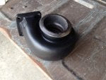
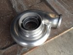
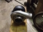
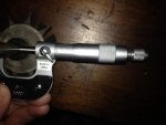
The turbo I’ll be trying is an S300 with a 1.10 A/R, T4 turbine housing. The compressor wheel measures about 64.5/91.4mm.The turbine measures about 76.2/67.6mm.In its original application it supported 285 HP with 30 psi of boost.I’ve smoothed out both the compressor and the turbine housing to make them look nice and I’m planning to ceramic coat the turbine housing and duracoat the compressor housing.

Progress on this thread will be a little slow since I have quite a few projects going on right now.

Pics:
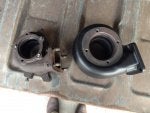
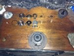
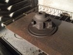
1. Test fit from a couple years ago
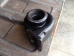
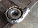
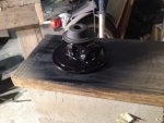
2. Turbine housing on spare manifold with adapter plate
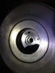
3. Shiny turbine housing
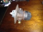
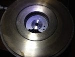
4. Shiny compressor housing
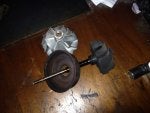
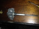
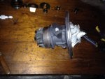
5. Blasted turbine, shiny compressor
 

Attachments

See less See more
5
#2 ·
Glad to see you are getting close, looking forward to seeing how/where this turbo spools. Still think the turbine is large, more in our thinking as a primary with a GM-X secondary in a compound set-up....
 
#8 ·
:think: perhaps we are missing something?:confuzeld
 
#4 ·
Good luck. Guys like you are a great benefit to guys like me!
 
#6 ·
Thanks! I've learned a lot from what others have posted. Just trying to give some back.

I'm really quite anxious to find out if the 6.5 can spin this thing up. We'll all find out together.
 
#5 ·
What were you going to use the truck for?
That should be a nice turbo for highway driving and towing.
 
#7 ·
The truck is my DD in the winter when the CBR gets parked. Spends most of the time on the freeway. Hauls wood. Plows snow. 4.10 gears and the 4L80 keep RPM over 2000 when loaded.
 
#13 ·
Like I have always said, there is no perfect turbo, it all comes down to how it's being driven & what it's being used for.. the link the fellas posted shows that.. no turbo can be considered best in every situation...

And James, if I wasn't a patient person I would have given up a long time ago on the P motor project...
 
#14 ·
Adapter Plate

Here are a couple photos of the adapter plate. I didn't take a lot of time with this. If this turbo works out ok, then I will likely be building an exhaust manifold/header with the correct flange for the turbo. Time will tell.
 

Attachments

#16 ·
Here are a couple photos of the adapter plate. I didn't take a lot of time with this. If this turbo works out ok, then I will likely be building an exhaust manifold/header with the correct flange for the turbo. Time will tell.
the adapter goes from the stock gm(T-3) to the new turbo, which is T-4, correct?
 
#15 ·
I'm just about set up to apply the turbo-X to the turbine housing. Hoping to get that done today. If things go really well, maybe I'll get the clearcoat on the compressor housing as well.
 
#17 ·
Yes.

Turbine is sprayed. Baking now. Will get some photos up in a bit.
 
#18 ·
Well, maybe I shouldn't say yes so quickly. I found a couple different dimensions online indicating T4. This turbine matches some drawings but not others. Still have that drawing I sent you? Maybe you can verify?
 
#20 ·
yeah, got it somewheres, but we did a big puter upgrade in january, and still have not went through our 2 TB external disk of pics and info, so i cant say where we have it, but to me it looks like a T4, it came from a JD 6068T didnt it? this engine was T4 for sure, as were most of the JD I6's......
 
#19 ·
I started out by making a stand for the housing so that I could spin it around for the best angle to spray it. Just grabbed some scrap from around the shop and tacked it together.


I test fit the turbine with stand in the oven before getting started. You would think that a turbine housing would fit easily in an oven, but it gets kind of tight. I did think to check this while I was building the stand so, I made the stand only as tall as it had to be.


I then cleaned it repeatedly with acetone, masked off the areas I didn't want coated, and put on a coating of the turbo-X. I sprayed it through an Iwata air brush with 40 psi. The control had to be pulled almost all of the way back to get any paint to flow and even then it flowed pretty slow. Next time I spray, I think I'll plan to thin it a bit.


Right now the turbine housing is baking in the oven (about 15 minutes left) and I'm preparing to spray some clear duracoat on the compressor.
 

Attachments

#22 ·
After a couple hours of baking, I shut the oven off and let it sit until this morning. I pulled it out before we headed to church this morning. Here are some photos of the result. I think it looks pretty nice, but I guess we'll see how it holds up. The other housing in the last two photos is the original GM-5. Whose idea was it to try something this big?
 

Attachments

#23 ·
The compressor housing doesn't look nearly as nice as the turbine. Part of the problem was the operator learning to use the air brush. Part of the problem was the operator contaminating the freshly applied coating with debris. I still have no idea where I kept picking up the debris, but it happened more than once. A more thorough cleaning of my work area would have made a huge difference. If you look close in the photos you can see all sorts of crap in the clearcoat. You can also see spots from where larger drops of clear hit the surface. I started spraying this at 40 psi, but then cut back to 30 which seemed to work much better. The duracoat did not require any thinning to spray easily through the air brush. It was much thinner than the turbo-x.
 

Attachments

#24 ·
It will be hard to see the imperfections in the compressor housing when you go rocketing by with the hood closed!
 
  • Like
Reactions: paleyjim
#25 ·
True.
This whole coating part of the project grew out of just grinding off the emblems and letter/numbers from the housing. I was going to just bolt it on as it was - old used turbo that had been sitting on my shelf for years. I should be happy it looks as good as it does - and I am, actually.
I'm not doing anything with the center section right now, so it isn't going to be very pretty anyway.
I did some poking around on the siliconintakes website last night to get some ideas for intake plumbing, but I didn't get anything ordered yet.
 
#26 ·
Looking good, James!

For the tune, I suspect we'll have some trial and error. There's a balance between keeping enough timing advance to maintain acceptable throttle response, and retarding it to get some heat to that housing! Your current tune will go in the trash except for the trans settings we worked on and will continue to tweak.

Are you going to wrap and/or coat your crossover pipe?

And don't worry too much about feedback from the DB2 crowd on how a turbo like yours will work unless you plan to swap to a DB2.
 
  • Like
Reactions: paleyjim
#28 ·
Looking good, James!

Thanks! I'm trying to at least do something on the project every night I've got a few more photos, but not sure I'll get them posted tonight.

For the tune, I suspect we'll have some trial and error. There's a balance between keeping enough timing advance to maintain acceptable throttle response, and retarding it to get some heat to that housing! Your current tune will go in the trash except for the trans settings we worked on and will continue to tweak.

That works for me. Just out of curiosity, I'm planning to run this turbo with my current tune as well as a factory tune to see how it acts. I'll be in contact with you as things get closer.

Are you going to wrap and/or coat your crossover pipe?

Yes. I will be wrapping it. Need to go back and review some Turbonator threads about exhaust insulation. Seems to me they have some ideas I liked. I do have some DEI titanium header wrap that I might use too.

And don't worry too much about feedback from the DB2 crowd on how a turbo like yours will work unless you plan to swap to a DB2.

Yeah the electronic pump can give you flexibility you just can't get with mechanical. We can't get the same amount of fuel, but we do have flexibility.
 
#27 ·
could be interesting to have a couple before and after dyno runs....
 
#29 ·
Agreed, but probably not going to happen. My GTECH data has proven to be unreliable, so I may not even bother with that either.


I did some searching a while back and found some dynos that aren't too far away. I think I made a list of possibilities and will have to see if I can find that list. I may make some calls and see what I can set up.


I would probably need custom trans programming to hold it in 3rd and keep the converter locked. Anybody got other suggestions?
 
#30 ·
Just a couple photos. Not a lot of progress, but I'm getting a little done.
-The turbo is loosely assembled until it can be bolted on and the housings properly clocked.
-The current status of the downpipe fabrication. I took a few measurements seems to indicate that this is going to be a VERY tight fit to the receiver dryer. I may have some rework to do.
-The downpipe flange mated up with the turbo. Fits pretty well.
-Vband clamp installed and snugged up.


I've also pulled the upper intake off and made a tracing of it in case I decide to fabricate a new one. I'm a bit up in the air about that yet. What I would like to build will challenge my fabrication skills.
 

Attachments

#31 · (Edited)
Well, I just couldn't bring myself to use the turbo without going through the bearing housing. I just ordered a rebuild kit from spturboost.com. I probably should have asked here first for a recommendation, but it is done. I'll post up pictures of the rebuild when it gets here.

I am hoping to work a little on the upper intake tonight, but will have to see what my wife has planned for me.
 
#32 ·
I am hoping to work a little on the upper intake tonight, but will have to see what my wife has planned for me.
Don't ask her.... tell her YOU need her help...LOL

And let us know how that works out for ya... and pics of the knot she gives ya....:clap:
 
#33 ·
She doesn't leave marks...
 
#35 ·
I got delayed by a couple things: I noticed a funny tear/crack in the steel I was using to fab the upper intake flange - so had to scrap that piece and start over. My hydroboost leak also started getting bad so that rebuild moved to the top of the list.


But here are some photos of the progress from last night. I pulled the compressor and turbine housings back off and stripped down the center section. This is the first time I've rebuilt a center section and I was amazed that the rebuild kit contained every removable part in the bearing housing. The parts are all lined up in order with the new parts matched up in the bottom row. I hosed the housing down well with brake cleaner and blew some high temp paint on it. It is still wet in the photo and will dry much flatter.
 

Attachments

#36 ·
I cleaned up the shaft with brake cleaner and a scotch bright pad and got the new sealing ring installed. Then called it a night. I hope to make some more progress on Friday.
 

Attachments

#37 ·
nice kit, comes with the up-graded 360 degree thrust plate, and the gapless ring for the turbine side of the CHRA... before you assemble it, if could please measure the outside diameter of the brass bearing/bushings, and the thickness of the turbine shaft where the bearings ride, and also where the compressor wheel rides on the shaft....
 
#39 ·
Not sure what kind of precision you are looking for. I probably should have just used the caliper. Grabbed these very quickly this morning before heading to work. I'll try to double check them before assembly. Sorry, no metric measuring tools.


Bearing OD: 0.7515"
Shaft Dia at bearings: 0.4567"
Shaft Dia at comp wheel: 0.3149"
 

Attachments

#38 ·
also i notice its a 6 sided nut for the compressor wheel, normally this indicates that it needs to be balanced by a machine, and is not component balanced, but dont worry, BW/schwitzer have an excellent track record of unbalanced rebuilds...
 
#40 ·
And a couple shots of the housing after baking last night...
 

Attachments

#41 ·
I got the center section back together last night. I just need to get some paint on the straps and bolt everything back together. A couple photos...
 

Attachments

Top