Here is what is need to do for the "Manual High Idle" function to work on the '06 and '07 LBZ engines
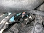
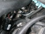
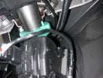
Location of the ECM
- the ECM is just below and under the upper radiator hose in the pictures
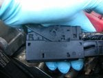
You have to remove the lower electrical connector first. There is a lever tab on the bottom of the connector that must be pulled up and towrads the fire wall. This will move almost 160* and you can now remove the lower connector.
- Could not any good pictures of this. You can barely see the lever tab in the out position about 90* in the middle of the picture.
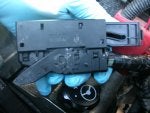
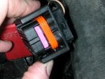
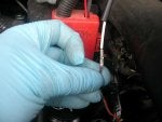
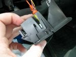
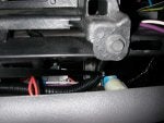
The upper electrical connector can now be remove. There is a lever tab on the top of the connector that has to be pushed down and towards the fire wall. This will move just about 180* and you can now remove the upper connector.
My fingers are on the lever tab.
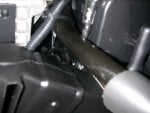
The surrounding wire looms will have to be moved out of the way to be able to get the lower and upper connectors out of their sockets.
Move the two ECM electrical connectors out from under the upper radiator hose to over the power steering pump/resevior.
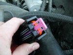
Now it is easy to see that the Lower Electrical connector is smaller that the Upper Electrical connector.
The larger Upper Electrical connector is the "C1" connector. This is the connector we will be working with.
The smaller Lower Electrical connector is "C2" and can be pushed back out of the way.
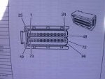
Using the information from the GMUPFITTER web site, locate the correct page showing the C1 connector for the '06 vehicles.
Here I have high lighted in pink the #8 and #60 pin location. Remember that this is looking at the face of the connector. Not the back side where the wires go in.
To access the back side of the conector, the cover has to be removed. Using a small flat blade screw driver CAREFULLY slide the screw driver under the end, between the cover and the body first. Then move to one side and insert the screw driver in the slot just to the side of the left and right clip and pry up. Repeat for the other side.
You should now see all the wires under the cover.
Remove the zip tie at the end of the connector. BE CAREFULL not to cut any of the wires while doing this.
Now to find the pin hole locations.
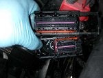
The #8 hole is located in the top row of the top section with the wires going out to the right side of the connector.
#8 is the empty hole between a PURPLE WIRE and a BROWN WIRE.
The #60 hole is located in the top row of the bottom section with the wirs going out to the right side of the connector.
#60 is the left side empty hole in between a GRAY WIRE #61 and a LIGHT GREEN WIRE #58
There is 2 empty holes here, the hole directly next to the GRAY WIRE is the one needed.
Picture is fuzzy, but you can still see the holes and wires.
The PINK BAR at the end of the connector needs to be removed to allow the new ECM pins to be installed correctly.
To remove the bar, a small flat blade screw driver is needed to be inserted into the groove at the center of the connector body to GENTLY pry up thePINK BAR.
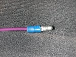
Now the new ECM pins can be installed in the previously located #8 and #60 holes.
I soldered my pins to stiffen them for easier install and to ensure a good connection, if the crimps dont look good.
Using a 1/16" Drift Pin Punch, insert the pins into the hole and press firmly until the pin is fully seated in the connector body.
- Sorry didn't get any pictures of this part.
For my install, the BLUE WIRE is in the #8 hole and the ORANGE WIRE is in the #60 hole.
Install a new zip tie at the end of the connector body, making sure that the zip tie is under the angle clip, to keep it from moving off the body.
Reinstall the connector cover/locking lever tab.
Cut the wires even, strip the ends log enough for a uninsulated butt crimp connector.
Using a piece of #16 AWG copper wire, slide a section of heat shrink tubing over the wire and strip the end long enough to fit into the butt connector.
You can soldered this connction at this point if you want to.
Slide the heat shrink tubing over the butt connector, making sure that the butt connector is cose to the ceter of the tubing section and using a small torch heat the tubing to shrink it into place and cover the connection. DO NOT BURN OR MELT THE WIRE!!
Run the now connected #16 AWG wire in a nearby piece of corrigated split loom up towards the firewall.
Reinstall the ECM Electrical connectors back onto the ECM.
The larger Upper Connector must be installe first, then the Lower connector can be installed.
Using a small section of Corigated Split Loom, cover/protect the new wire from the ECM to the other section of split loom you ran the wire in to get to the firewall.
Secure the loom and wire with zip ties. You can see the untrimmed zip ties in the photo.
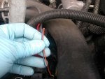
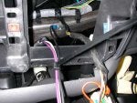
Where I ran my wire thru the fireall using a existing hole.
YOU HAVE NOW COMPLETED THE UNDERHOOD PORTION OF THIS INSTALL.
LETS MOVE TO THE CAB INSTALL SECTION.
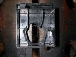
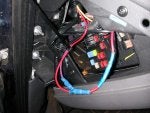
Locate the drivers side fuse block and find a "Keyed on" fuse.
I used the 10 AMP "TCB ACCY" fuse.
Using a Auto Tap Fuse Adder for my EGT and Boost Guage install, I left a tap in point for future use, knowing that I would be doing this Mod.
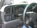
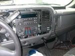
Remove the Dash Trim
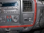
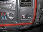
Choose a suitable location for your new switch.
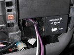
I chose the empty/blank space to the left of the Passenger Air Bar On/Off Key Switch.
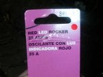
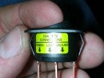
For my switch I used a small round rocker style with a red LED
To remove the Air Bag switch assembly, GENTLY PULL on the top corners of the large blank space above the Key Switch. You will feel a small pop. Now GENTLY PULL on the bottom corners os the assemebly.
To remove the small blank space section, use a small flat blade screw driver under the clip and GENTLY PRY UP. The piece will come out with a GENTLE FIRM PULL once the clip is released.
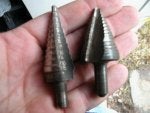
Usig a UNIBIT I drilled a 15/16" hole for the switch, the instructions on the switch package.
After drilling the hole, clean out the "Structual" ribs on the back side of the piece.
Switch installed in blank piece.
Guesstimate the amount of wire needed to get from the fuse block to your new switch location.
Run the new "feed" ( from fuse ) wire and the new "load" ( from ECM ) wire inside a piece of corrigated split loom under the dash to the switch location.
Use zip ties to secure the split loom along the route taken, you can see the untrimmed ends in the pictures.
Using a round male crimp on the end of the "feed" wire, connect to the fuse tap.
Find a suitable location for the ground wire to connect to. I used the "Structual" Dash Bar for my location.
Using a #10 SELF DRILLING SCREW with a 5/16" HEX DRIVE HEAD, I fed the Ring Terminal Crimp onto the screw and installed.
Secure all 3 wires together witha zip tie.
Cut the ends of the wires even with each other.
Feed the wires thru the "Keyed Switch Assembly" and reinstall the assembly back onto the dash.
Install 1/4" FEMAL SPADE CRIMP CONNECTORS on the ends of the wires.
Knowing which way the wires need to go onto the switch, install the Femal Spades onto the switch.
Install the Blank space with the switch and wires now installed back into the "Keyed Switch" assembly.
Reinstall "Dash Trim"
Go back check all electrical connectors and connections, to make sure every one is secure.
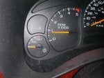
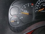
Start vehicle and check guages and idle speed.
Idle speed should be around 650-700 RPM.
Turn switch "ON"
Idle should now be 800 RPM
Push the "SET CRUISE" button, Idle should now be 1200-1300 RPM
Push the "ACCEL CRUISE" button, Idle should now be 1700-1800 RPM
Apply the BRAKE PEDAL at any time and the RPM should drop to 650-700 RPM.
Turn the HIGH IDLE SWITCH "OFF" and Idle should drop to 650-700 RPM
Now you can enjoy a warm or cool truck any time of the year and at any outside air intake temperature.
LtEng5
The attached pics follow in order of the instructions. I couldnt get them to install in the text correctly. Hopefully a MOD can insert them where they need to go.
Location of the ECM
- the ECM is just below and under the upper radiator hose in the pictures
You have to remove the lower electrical connector first. There is a lever tab on the bottom of the connector that must be pulled up and towrads the fire wall. This will move almost 160* and you can now remove the lower connector.
- Could not any good pictures of this. You can barely see the lever tab in the out position about 90* in the middle of the picture.
The upper electrical connector can now be remove. There is a lever tab on the top of the connector that has to be pushed down and towards the fire wall. This will move just about 180* and you can now remove the upper connector.
My fingers are on the lever tab.
The surrounding wire looms will have to be moved out of the way to be able to get the lower and upper connectors out of their sockets.
Move the two ECM electrical connectors out from under the upper radiator hose to over the power steering pump/resevior.
Now it is easy to see that the Lower Electrical connector is smaller that the Upper Electrical connector.
The larger Upper Electrical connector is the "C1" connector. This is the connector we will be working with.
The smaller Lower Electrical connector is "C2" and can be pushed back out of the way.
Using the information from the GMUPFITTER web site, locate the correct page showing the C1 connector for the '06 vehicles.
Here I have high lighted in pink the #8 and #60 pin location. Remember that this is looking at the face of the connector. Not the back side where the wires go in.
To access the back side of the conector, the cover has to be removed. Using a small flat blade screw driver CAREFULLY slide the screw driver under the end, between the cover and the body first. Then move to one side and insert the screw driver in the slot just to the side of the left and right clip and pry up. Repeat for the other side.
You should now see all the wires under the cover.
Remove the zip tie at the end of the connector. BE CAREFULL not to cut any of the wires while doing this.
Now to find the pin hole locations.
The #8 hole is located in the top row of the top section with the wires going out to the right side of the connector.
#8 is the empty hole between a PURPLE WIRE and a BROWN WIRE.
The #60 hole is located in the top row of the bottom section with the wirs going out to the right side of the connector.
#60 is the left side empty hole in between a GRAY WIRE #61 and a LIGHT GREEN WIRE #58
There is 2 empty holes here, the hole directly next to the GRAY WIRE is the one needed.
Picture is fuzzy, but you can still see the holes and wires.
The PINK BAR at the end of the connector needs to be removed to allow the new ECM pins to be installed correctly.
To remove the bar, a small flat blade screw driver is needed to be inserted into the groove at the center of the connector body to GENTLY pry up thePINK BAR.
Now the new ECM pins can be installed in the previously located #8 and #60 holes.
I soldered my pins to stiffen them for easier install and to ensure a good connection, if the crimps dont look good.
Using a 1/16" Drift Pin Punch, insert the pins into the hole and press firmly until the pin is fully seated in the connector body.
- Sorry didn't get any pictures of this part.
For my install, the BLUE WIRE is in the #8 hole and the ORANGE WIRE is in the #60 hole.
Install a new zip tie at the end of the connector body, making sure that the zip tie is under the angle clip, to keep it from moving off the body.
Reinstall the connector cover/locking lever tab.
Cut the wires even, strip the ends log enough for a uninsulated butt crimp connector.
Using a piece of #16 AWG copper wire, slide a section of heat shrink tubing over the wire and strip the end long enough to fit into the butt connector.
You can soldered this connction at this point if you want to.
Slide the heat shrink tubing over the butt connector, making sure that the butt connector is cose to the ceter of the tubing section and using a small torch heat the tubing to shrink it into place and cover the connection. DO NOT BURN OR MELT THE WIRE!!
Run the now connected #16 AWG wire in a nearby piece of corrigated split loom up towards the firewall.
Reinstall the ECM Electrical connectors back onto the ECM.
The larger Upper Connector must be installe first, then the Lower connector can be installed.
Using a small section of Corigated Split Loom, cover/protect the new wire from the ECM to the other section of split loom you ran the wire in to get to the firewall.
Secure the loom and wire with zip ties. You can see the untrimmed zip ties in the photo.
Where I ran my wire thru the fireall using a existing hole.
YOU HAVE NOW COMPLETED THE UNDERHOOD PORTION OF THIS INSTALL.
LETS MOVE TO THE CAB INSTALL SECTION.
Locate the drivers side fuse block and find a "Keyed on" fuse.
I used the 10 AMP "TCB ACCY" fuse.
Using a Auto Tap Fuse Adder for my EGT and Boost Guage install, I left a tap in point for future use, knowing that I would be doing this Mod.
Remove the Dash Trim
Choose a suitable location for your new switch.
I chose the empty/blank space to the left of the Passenger Air Bar On/Off Key Switch.
For my switch I used a small round rocker style with a red LED
To remove the Air Bag switch assembly, GENTLY PULL on the top corners of the large blank space above the Key Switch. You will feel a small pop. Now GENTLY PULL on the bottom corners os the assemebly.
To remove the small blank space section, use a small flat blade screw driver under the clip and GENTLY PRY UP. The piece will come out with a GENTLE FIRM PULL once the clip is released.
Usig a UNIBIT I drilled a 15/16" hole for the switch, the instructions on the switch package.
After drilling the hole, clean out the "Structual" ribs on the back side of the piece.
Switch installed in blank piece.
Guesstimate the amount of wire needed to get from the fuse block to your new switch location.
Run the new "feed" ( from fuse ) wire and the new "load" ( from ECM ) wire inside a piece of corrigated split loom under the dash to the switch location.
Use zip ties to secure the split loom along the route taken, you can see the untrimmed ends in the pictures.
Using a round male crimp on the end of the "feed" wire, connect to the fuse tap.
Find a suitable location for the ground wire to connect to. I used the "Structual" Dash Bar for my location.
Using a #10 SELF DRILLING SCREW with a 5/16" HEX DRIVE HEAD, I fed the Ring Terminal Crimp onto the screw and installed.
Secure all 3 wires together witha zip tie.
Cut the ends of the wires even with each other.
Feed the wires thru the "Keyed Switch Assembly" and reinstall the assembly back onto the dash.
Install 1/4" FEMAL SPADE CRIMP CONNECTORS on the ends of the wires.
Knowing which way the wires need to go onto the switch, install the Femal Spades onto the switch.
Install the Blank space with the switch and wires now installed back into the "Keyed Switch" assembly.
Reinstall "Dash Trim"
Go back check all electrical connectors and connections, to make sure every one is secure.
Start vehicle and check guages and idle speed.
Idle speed should be around 650-700 RPM.
Turn switch "ON"
Idle should now be 800 RPM
Push the "SET CRUISE" button, Idle should now be 1200-1300 RPM
Push the "ACCEL CRUISE" button, Idle should now be 1700-1800 RPM
Apply the BRAKE PEDAL at any time and the RPM should drop to 650-700 RPM.
Turn the HIGH IDLE SWITCH "OFF" and Idle should drop to 650-700 RPM
Now you can enjoy a warm or cool truck any time of the year and at any outside air intake temperature.
LtEng5
The attached pics follow in order of the instructions. I couldnt get them to install in the text correctly. Hopefully a MOD can insert them where they need to go.