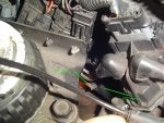
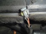
I finally got around to doing my OPS relay today. I found in the search that there weren’t any pics of this so took my camera along and snapped some. The first pic is of the OPS location. The second pic is of the OPS plug and the wire colors. The third pic is of the items I used to do the project. The fourth pic is of the wires cut and crimped.
The length of the extension wires were 24“, I removed the convoluted tubing from the OPS wires before I started cutting. my wire colors for the relay extension were :
Orange for the hot: I cut the orange wire from the OPS plug about 3” from the plug and tied in the orange extension wire. Crimped and shrink wrapped it.
Gray for the OPS plug: approximately 2.5” from the plug I cut the gray wire. The wire from the OPS plug I connected the gray extension wire. Crimped and shrink wrapped.
Light purple for the LP: on the cut wire going to the LP I connected the Purple wire. Crimped and shrink wrapped.
Brown for the ground: The brown ground wire is much shorter because it is just ran to the relay’s mounting screw.
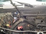
My pics don’t show the shrink wrap installed on the wires (I thought I had took one but this was the time the grandson decided to interrupt me). The fifth pic is of the wires from the OPS re-loomed and the relay wires Loomed. I decided to mount the relay under the electric shroud pic # 6 on the passenger’s firewall pic # 7 . It seemed to be the most likely place to put it. Being that the factory saw fit to have already put holes there and the other relays were there as well. I mounted the ground with the same screw I mounted the relay with. Then replaced the shroud.
The relay is numbered and the extension wires hook to the relay in this order. #30 is the orange power wire (by the way this wire is hot with key off don’t let it ground out. Please don‘t ask how I know). #85 is the brown ground wire, #86 is the gray wire from the OPS and #87 is the purple wire to the LP.
Staff Edit:
Oil Pressure Switch: Replace OPS with AC Delco D1808A
Relay Parts Options:
Relay: NAPA - AR143
Relay Connector: NAPA - ECH EC23 or Relay Connector (with mounting bracket): NAPA - ECH EC38
"Marine" weather proof crimp connectors with heat shrink "built in". Available at O'reillys and other parts stores. Use heat gun. Sample: Click Here. These connectors are available in smaller quantities.
1992-1994 Trucks: Instead of tapping the Orange wire, get 12v for the relay from the Power Block located on the passenger side of the firewall.
Remaining pics in post 2
The length of the extension wires were 24“, I removed the convoluted tubing from the OPS wires before I started cutting. my wire colors for the relay extension were :
Orange for the hot: I cut the orange wire from the OPS plug about 3” from the plug and tied in the orange extension wire. Crimped and shrink wrapped it.
Gray for the OPS plug: approximately 2.5” from the plug I cut the gray wire. The wire from the OPS plug I connected the gray extension wire. Crimped and shrink wrapped.
Light purple for the LP: on the cut wire going to the LP I connected the Purple wire. Crimped and shrink wrapped.
Brown for the ground: The brown ground wire is much shorter because it is just ran to the relay’s mounting screw.
My pics don’t show the shrink wrap installed on the wires (I thought I had took one but this was the time the grandson decided to interrupt me). The fifth pic is of the wires from the OPS re-loomed and the relay wires Loomed. I decided to mount the relay under the electric shroud pic # 6 on the passenger’s firewall pic # 7 . It seemed to be the most likely place to put it. Being that the factory saw fit to have already put holes there and the other relays were there as well. I mounted the ground with the same screw I mounted the relay with. Then replaced the shroud.
The relay is numbered and the extension wires hook to the relay in this order. #30 is the orange power wire (by the way this wire is hot with key off don’t let it ground out. Please don‘t ask how I know). #85 is the brown ground wire, #86 is the gray wire from the OPS and #87 is the purple wire to the LP.
Staff Edit:
Oil Pressure Switch: Replace OPS with AC Delco D1808A
Relay Parts Options:
Relay: NAPA - AR143
Relay Connector: NAPA - ECH EC23 or Relay Connector (with mounting bracket): NAPA - ECH EC38
"Marine" weather proof crimp connectors with heat shrink "built in". Available at O'reillys and other parts stores. Use heat gun. Sample: Click Here. These connectors are available in smaller quantities.
1992-1994 Trucks: Instead of tapping the Orange wire, get 12v for the relay from the Power Block located on the passenger side of the firewall.
Remaining pics in post 2